How to Calibrate Capacitive Fuel Sensors for Dual-Tank Heavy Trucks in 5 Steps
Table of Contents
- Why Dual-Tank Fuel Calibration Requires Special Procedures
- The 5-Step Engineering Calibration Procedure
- Calibration Accuracy Benchmark: Factory Float vs. Calibrated Probe
- Questions to Ask Your Telematics Calibration Partner
- Achieve ±0.2% Fuel Precision Across Your Fleet
- Related Articles
- Explore WizIOT Solutions
E-Mobility & EV Fleets Telematics
WizIOT EV-BMS Telematics Controller + CAN-bus J1939 / CANopen Sniffer
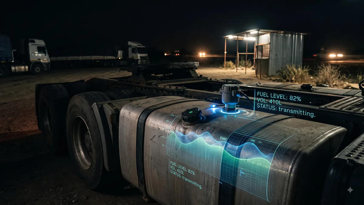
A workshop supervisor at a commercial transport depot in Nairobi finishes installing two digital fuel probes into the 500-liter dual aluminum tanks of a heavy long-haul tractor unit. However, after filling the tanks, the telematics software reads 820 liters instead of 1,000 liters—and during cornering, the system triggers constant false siphoning alarms.
In commercial fleet fuel monitoring, a fuel probe is only as accurate as its calibration table. Installing high-precision capacitive sensors without performing multi-point volumetric calibration creates measurement drift, false theft notifications, and loss of driver trust.
If your technical team or telematics partner is deploying in-tank fuel sensors on dual-tank commercial vehicles, following standard single-point calibration will fail. This comprehensive guide details the 5-step engineering calibration procedure required for sub-liter volume accuracy.
---
Why Dual-Tank Fuel Calibration Requires Special Procedures
Heavy commercial haulage trucks (e.g., Mercedes Actros, Scania R-series, Volvo FH, Isuzu FYR) frequently carry dual fuel tanks (main and auxiliary) connected by a bottom equalizer pipe or top fuel transfer pump.
Dual-tank fuel monitoring presents distinct volumetric calibration challenges:
1. **Non-Linear Tank Geometries:** Fuel tanks are rarely perfect rectangles; rounded corners, step cutouts for battery boxes, and internal baffle plates alter the volume-to-height ratio at different fill levels. 2. **Equalizer Flow Lag:** When fuel is added to the main tank, it takes several minutes to flow through the narrow equalizer hose into the auxiliary tank, creating transient volume imbalances. 3. **Slope & Inclination Distortions:** Parking on an uneven grade causes fuel to pool in one tank, producing false single-tank drop readings if sensors are evaluated independently rather than mathematically summed.
---
The 5-Step Engineering Calibration Procedure
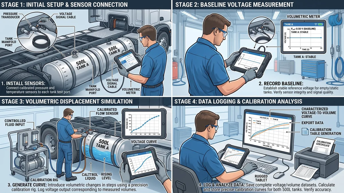
Step 1: Pre-Calibration Sensor Trimming & Signal Nulling
Before inserting the capacitive probe into the tank, the probe length must be trimmed to match tank depth (leaving a 15 mm gap at the bottom to prevent water sludge short circuits).
- **Dry Value Calibration (Min Voltage):** Hold the dry probe in ambient air and log the base electrical frequency/voltage (e.g., 0.50 V or 1000 Hz).
- **Full Immersion Value (Max Voltage):** Submerge the probe completely in a pipe filled with clean diesel fuel and log the maximum frequency/voltage (e.g., 4.50 V or 4000 Hz).
- **Firmware Nulling:** Store dry and wet calibration values into sensor non-volatile memory before physical tank installation.
Step 2: Tank Drainage & Zero Baseline Logging
Drive the truck onto a flat, level concrete bay inside the workshop. Drain both main and auxiliary fuel tanks completely using a fuel transfer pump until fuel flow stops.
Turn on the vehicle telematics unit and log the baseline voltage reading for both Probe A (Main) and Probe B (Auxiliary) under zero-volume state.
Step 3: Multi-Point Volumetric Fuel Pouring (10-Step Calibration)
Fill the fuel tanks incrementally using a certified volumetric fuel meter or calibrated 50-liter dispensing nozzle.
- **Incremental Step Size:** Add fuel in precise 50-liter increments (e.g., 0L, 50L, 100L, 150L ... up to 1,000L).
- **Settling Time Window:** Wait 3 minutes after each 50-liter addition to allow fuel levels to equalize between main and auxiliary tanks.
- **Voltage Table Logging:** Record exact voltage outputs for Probe A and Probe B at each 50-liter increment into the calibration software table.
Step 4: Software Calibration Curve Interpolation
Raw capacitive sensor output is linear (voltage vs. height), but tank volume vs. height is non-linear. The WizIOT software uses piecewise cubic Hermite interpolating polynomials (PCHIP) to construct a custom volumetric lookup table for both tanks.
The software mathematically sums Probe A + Probe B volume in real time:
$$\text{Total Fuel Volume} = V_A(h_A) + V_B(h_B)$$
Where $V_A$ and $V_B$ are volume lookup functions derived from the multi-point calibration table.
Step 5: Slope Tilt Filter & Dynamic Motion Verification
Configure software Kalman filtering parameters to smooth out dynamic fuel sloshing during acceleration and braking. Set a 3-axis accelerometer tilt threshold (up to 12 degrees) so that fuel redistributions on steep slopes do not trigger false theft alarms.
---
Calibration Accuracy Benchmark: Factory Float vs. Calibrated Probe
| Measurement Feature | Factory Arm Float Sensor | WizIOT Calibrated Capacitive Probe | |---|---|---| | **Measurement Precision** | ±12.0% to ±18.0% | **±0.2% to ±0.5%** | | **Sub-Liter Resolution** | No (Step jumps of 15L+) | **Yes (0.2 Liter resolution)** | | **Temperature Compensation** | None | **Built-in digital thermal sensor** | | **Dual Tank Volume Summation** | Indicated as separate vague gauges | **Mathematical total volume summation** | | **False Alarm Rate** | High (Slosh & slope spikes) | **Zero (Filtered static volume)** |
---
Questions to Ask Your Telematics Calibration Partner
1. *Do your field installers use certified volumetric meters during tank calibration?* 2. *How many calibration points are logged into the sensor lookup table (is it 10 points or more)?* 3. *Does your software automatically sum main and auxiliary dual-tank fuel volumes?* 4. *Do you provide a formal Calibration Certificate detailing voltage-to-liter curves post-install?* 5. *Does the probe feature automatic internal temperature compensation for diesel expansion?*
---
Achieve ±0.2% Fuel Precision Across Your Fleet
Stop suffering from false fuel theft alarms and inaccurate tank gauges. Partner with WizIOT for certified field installation, capacitive probe hardware, and multi-point tank calibration.
Book Telematics Calibration Service
---
Frequently Asked Questions (FAQs)
**Q1: How often should capacitive fuel probes be recalibrated?** Capacitive probes retain calibration stability for years. Recalibration is only necessary if a fuel tank suffers structural denting or if the sensor probe is replaced.
**Q2: Can temperature changes alter fuel probe calibration readings?** Diesel expands by approximately 0.08% per degree Celsius. WizIOT capacitive probes feature internal temperature sensors that automatically adjust volume calculations across temperature shifts.
**Q3: What happens if biodiesel or low-sulfur diesel is introduced into the tank?** Biodiesel has a slightly different dielectric constant than standard petrodiesel. WizIOT firmware includes a single-click fuel dielectric offset parameter to maintain ±0.2% accuracy across fuel blends.
**Q4: Can we calibrate fuel tanks without draining them completely?** For maximum accuracy, initial 10-point calibration requires starting from an empty tank baseline. However, pre-calibrated tank geometry profiles can be loaded into software for standard OEM truck models.
---
Related Articles
- Fuel Sensor Installation Cost Kenya: Per-Truck Pricing Breakdown & ROI Calculator (2026)
- CAN-Bus Fuel Consumption vs. In-Tank Fuel Probes: Which Delivers True Accuracy?
- How to Calculate Your Fleet’s Fuel Theft ROI & Payback Period in 10 Minutes
- Fuel Theft Monitoring: Real-Time Sensor Data That Caught 34 Drivers in 90 Days (SA Case Study)
---
Explore WizIOT Solutions
Target Telematics Hubs & Enterprise Solutions
Protect Your Commercial Fleet Today
Request a live hardware demonstration, ±0.2% capacitive probe calibration certificates, and real-time anti-theft gateway trials.